

Type A Girder Clamp
Standard girder clamp used to quickly connect steel beams with parallel / flat flanges and resist moderate tensile loading.
Overview
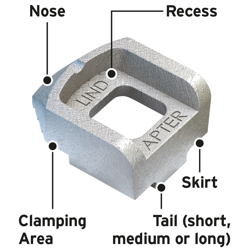
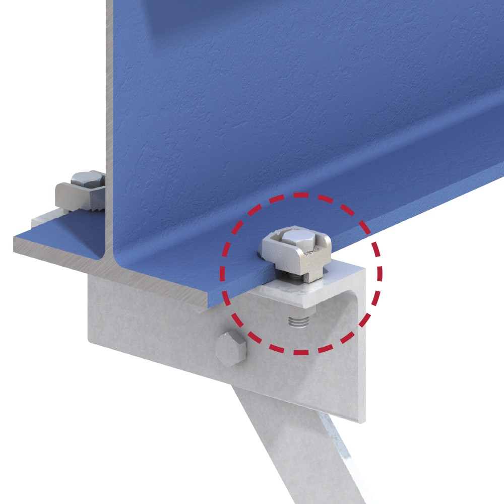
The Type A girder clamp is used to achieve a fast steelwork fixing connection between two steel beams and is often used in a pair with Type B clamps. It has a recessed top to hold the bolt head captive while the nut and washer are tightened down using only one tool. The skirt on the underside of the clamp abuts the edge of the beam flange and prevents the clamp rotating during installation. Type A girder clamps can also be used on their own if one piece of the steelwork has been pre-drilled.
Features & Benefits
- Recessed top holds the bolt captive while the nut is tightened.
- Ideal for parallel flanges.
- Supports up to 78.8kN tensile in a four-bolt configuration.
- Independently approved for dynamic load applications to EN 1993-1-9. Contact us for more details.
Approvals
Click on an approval logo to download the certificate or report.


Tail Lengths & Packing Pieces
The clamp is available in three tail lengths, Short, Medium and Long and can be used with Lindapter packing pieces to increase the clamping range. Choose the correct combination of tail length and packing pieces to suit a specific flange thickness. Download datasheet for selection table.
Location & End Plates
These plates ensure the clamps and bolts are located in the correct position relative to the supporting steelwork. Location plates are simple fabricated items designed to sit between the two sections to be clamped together to ensure the bolts are fixed at the correct centres. End plates are simple fabricated items that are pre-welded to support frames, bracket or sections, allowing connection to the supporting structure with standard Lindapter clamps. Download datasheet for further information.
Properties
- Manufactured from malleable iron to BS EN 1562.
- Available with zinc plated or hot dip galvanised finish.
- Reaction to fire: A1 (Steel)
Durability and corrosion protection:
| Corrosivity Class | Galvanised Steel | Electroplated Steel |
|---|---|---|
| C1 | More than 50 years | More than 20 years |
| C2 | More than 50 years | More than 5 years |
| C3 | More than 20 years | Not suitable |
For C4 and C5 corrosion categories contact us.
Technical Specification
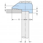

| Safe Working Loads (FOS 5:1) | Dimensions | ||||||||||
|---|---|---|---|---|---|---|---|---|---|---|---|
| Product Code | Bolt 8.8 Z | Tensile / 1 Bolt | Slip / 2 Bolts | Tightening Torque* | Y | X | Tail Length V | T | Width | ||
| short | medium | long | |||||||||
| kN | kN | Nm | mm | mm | mm | mm | mm | mm | mm | ||
| A08 | M8 | 1.0 | - | 6 | 16 | 8 | - | 4 | - | 4 | 20 |
| A10 | M10 | 1.5 | - | 20 | 20 | 11 | 4 | 5 | 7 | 5 | 26 |
| A12 | M12 | 5.8 | 0.9 | 69 | 26 | 13 | 4.5 | 6 | 9.5 | 6 | 29 |
| A16 | M16 | 8.5 | 1.7 | 147 | 30 | 16 | 5.5 | 8 | 11 | 8 | 36 |
| A20 | M20 | 14.7 | 3.0 | 285 | 36 | 19 | 7 | 10 | 12.5 | 10 | 46 |
| A24 | M24 | 19.7 | 4.5 | 491 | 48 | 29 | 9 | 12 | 16 | 13 | 55 |
* Torque figures based on bolts / setscrews in an unlubricated condition.
Suitable for UPN / IPN type tapered flanges. For further information contact Lindapter Technical Support.
![]() For Characteristic Resistances when designing a connection to Eurocode 3, please refer to DoC No.103
For Characteristic Resistances when designing a connection to Eurocode 3, please refer to DoC No.103
![]() For Characteristic Resistances when designing a connection to Eurocode 3, please refer to DoP No.003
For Characteristic Resistances when designing a connection to Eurocode 3, please refer to DoP No.003


How can we
help you?


Reasons to choose Lindapter
-

Save time and money
Clamping two steel sections together avoids time-consuming welding or conventional drilling and bolting.
-

Safer connections
On-site drilling and welding is avoided, removing the need for hot work permits and encouraging safer site conditions.
-

High strength
Lindapter clamps are manufactured from high strength materials to resist high load requirements and harsh environments.
-

Industry leading approvals
Lindapter has earned a reputation synonymous with safety and reliability, gaining multiple independent approvals.
-

Adjustable
Quickly align steel sections by sliding the section into the correct position before tightening the Girder Clamp to complete the installation.
-

Free connection design
Lindapter’s experienced Engineers can design a bespoke connection based on your specific requirements free of charge.
You must have a Lindapter account to access this content
Log in to your account
Register for an account
Don't have an account?
Click here to registerAlready registered?
If you have registered for an account but have not received your confirmation email, please click here to resend.
Headquarters
Lindapter InternationalLindsay House, Brackenbeck Road
Bradford, West Yorkshire
BD7 2NF
United Kingdom Map and directions
news
- Environmental Policy
- T&Cs
- Privacy
- Cookies
- © Lindapter International 2026. All rights reserved.